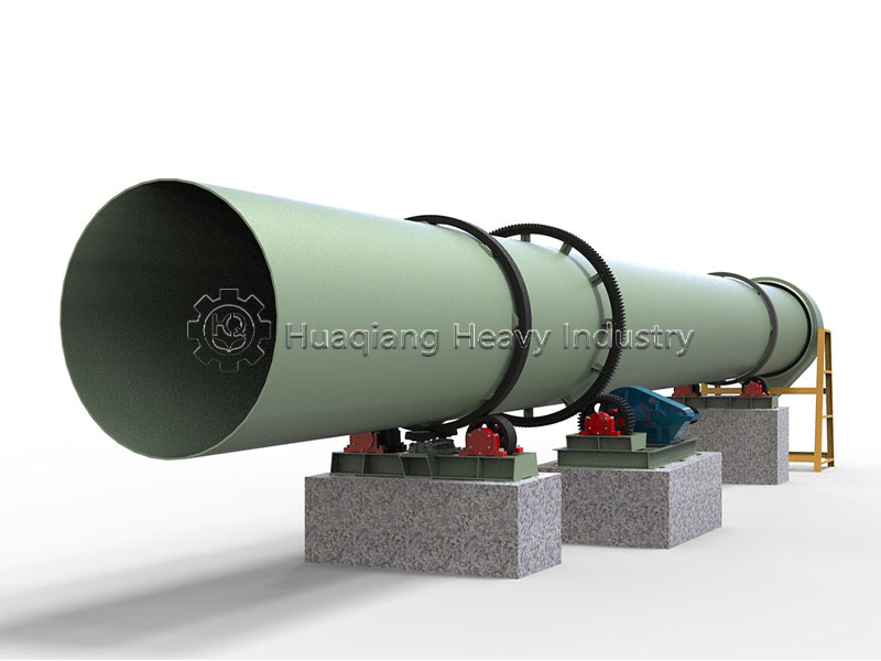
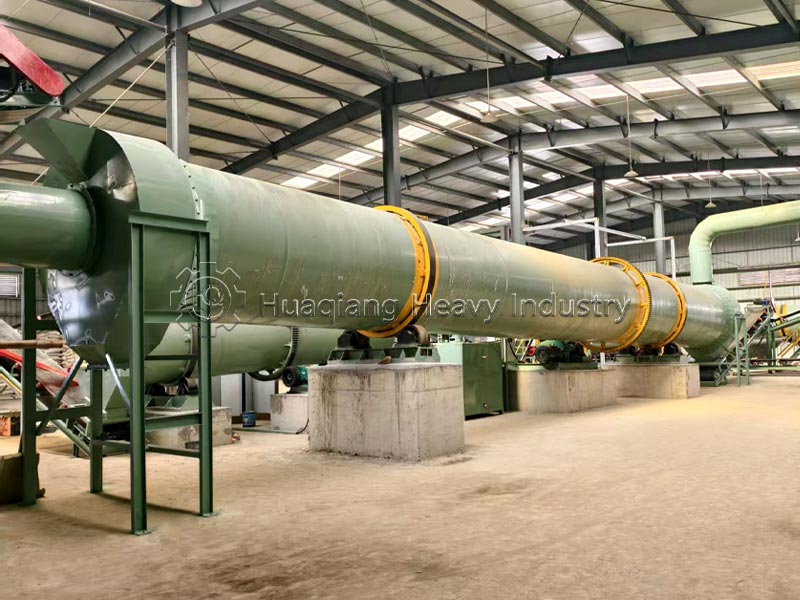
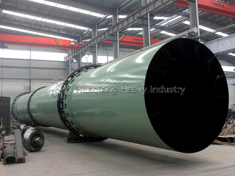
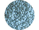
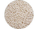
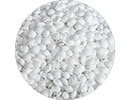
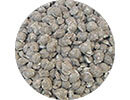
The drum fertilizer cooler—also known as a drum cooler—is a critical piece of equipment used alongside the dryer in the production of compound and organic fertilizers. Its primary function is clear: to rapidly lower the temperature of hot, freshly dried fertilizer granules while simultaneously removing residual moisture, thereby making the granules harder and more stable during the cooling process.
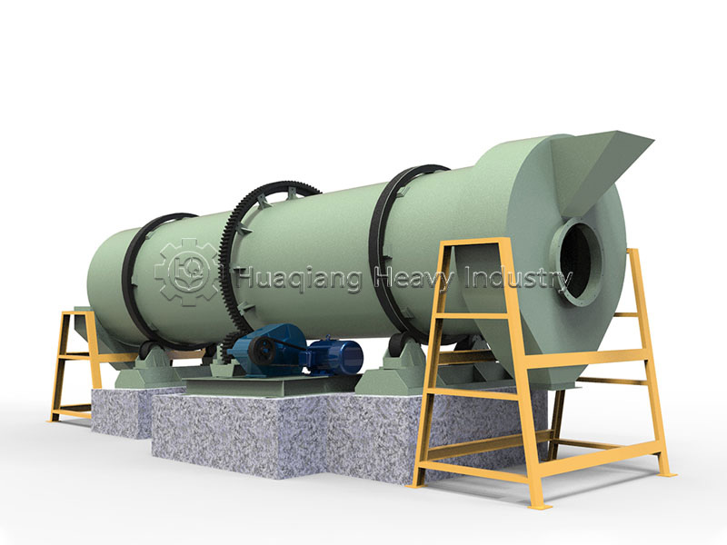
In terms of appearance, the drum cooler is virtually identical to the drum dryer; both consist of a large-diameter rotating cylinder mounted at an incline on a support roller assembly and driven by a motor to rotate slowly. However, the operating media differ: the dryer utilizes a flow of hot air, whereas the cooler uses cold air. It is precisely this distinction that dictates their respective roles within the production line.
A standard drum fertilizer cooler consists primarily of the following major components:
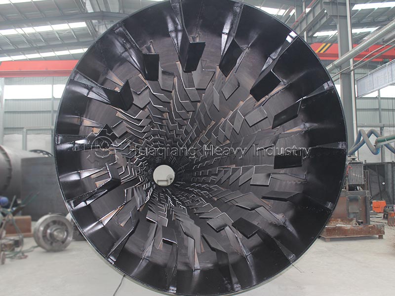
The drum assembly forms the “body” of the equipment; it is a large rotating cylinder, typically fabricated by rolling and welding steel plates. Lifting flights are arranged systematically inside the drum; their angles and layout patterns vary by manufacturer, which directly impacts cooling efficiency.
The drive assembly serves as the power source, comprising a motor, a gearbox, a pinion gear on the drive shaft, and a large girth gear fixed to the drum. The motor drives the gearbox, which rotates the entire drum slowly through gear meshing. The rotational speed is generally around 4.6–5 rpm.
The support roller assembly bears the weight of the drum. The drum rests on thrust rollers and support roller assemblies via front and rear riding rings (tires). It is installed at an inclination of 2-5°; this slope, combined with the drum's rotation, facilitates the slow conveyance of material from the feed end to the discharge end.
The feed and discharge assemblies include the feed hood, discharge hood, and their respective feed pipes, discharge pipes, and exhaust ducts. The feed end connects to the air inlet pipe, while the discharge end connects to the exhaust duct, creating a complete airflow path.
The typical production sequence for organic fertilizer derived from livestock and poultry manure is as follows: raw material fermentation— crushing (using a semi-wet material crusher) — mixing/blending — granulation (using a disc or rotary drum granulator) —high-temperature drying (drum dryer) — cooling (drum fertilizer cooler) — screening — anti-caking treatment (coating machine) — finished product packaging.
Cooling serves as a critical intermediate step between granulation and packaging. If cooling is skipped and the product is packaged directly, high-temperature moisture becomes trapped inside the bags; this frequently leads to issues such as moisture re-absorption, clumping, bag bulging, and mold growth, resulting in significant losses of the finished product.
Q: Must the cooler be used in conjunction with a dryer?
A: In the vast majority of cases, a dryer is required. Wet granules produced during granulation are at ambient temperature and do not require cooling; only the high-temperature granules discharged from the dryer need a drum cooler to dissipate heat. In rare instances involving hot materials from high-temperature fermentation, cooling equipment may be used independently.
Q: Why does the fertilizer temperature fail to meet standards after cooling?
A: Common causes include: insufficient fan airflow, excessive drum rotation speed (resulting in a short material retention time), excessively high discharge temperature from the dryer, or dust blockages in the air ducts. Solutions include reducing the drum rotation speed, cleaning the dust removal ducts, or upgrading to a higher-power induced draft fan.
Q: How should excessive dust generation during the cooling process be handled?
A: Standard configurations include a cyclone dust collector and flexible sealed connections at the material inlet and outlet points; additionally, a bag-type dust collector can be installed in the workshop to handle exhaust dust.
| Model | shell | Feed temperature | Discharge temperature | Motor | Decele vators model | |||||
| Inner diam | Length | Inclination | Rotation speed | Model | Power | Rotation speed | ||||
| mm | mm | (0) | r/min | °C | °C | kW | r/min | |||
| LQ10100 | 1000 | 10000 | 2-5 | 4.6 | 60-80 | <40 | Y132m-4 | 7.5 | 1440 | ZQ350 |
| LQ12120 | 1200 | 12000 | 2-5 | 4.6 | 60-80 | <40 | Y132m-4 | 7.5 | 1440 | ZQ350 |
| LQ15120 | 1500 | 12000 | 2-5 | 5 | 60-80 | <40 | Y160L-4 | 15 | 1440 | ZQ400 |
| LQ15150 | 1500 | 15000 | 2-5 | 5 | 60-80 | <40 | Y160L-4 | 15 | 1440 | ZQ500 |
| LQ18160 | 1800 | 16000 | 2-5 | 5 | 60-80 | <40 | Y200 L1-6 | 18.5 | 970 | ZQ500 |
| LQ20200 | 2000 | 20000 | 2-5 | 5 | 60-80 | <40 | Y200 L1-6 | 22 | 970 | ZQ650 |
A fertilizer coating machine is specialized equipment designed to coat the surface of fertilizer granules.
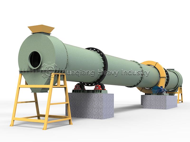
The drum fertilizer dryer utilizes the rotation of the drum to convey material and employs hot air for heat exchange to dry the fertilizer; it offers uniform drying and high production capacity, making it suitable for various types of organic fertilizer processing.